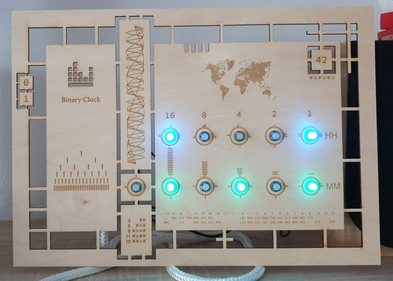
The current version of my binary clock.
Features
- Automatic synchronization using Network Time Protocol (NTP)
- High precision of one second via RTC
- Web-Interface for changing display mode (time / date) and brightness
How to Build
Bill of Materials
I have built this binary clock using
- Pycom WiPy 3.0
- Pycom WiPy 3.0 Expansion Board
- Adafruit 12mm diffuse LEDs (WS2801 chip), flat, strand of 25
- A3 3mm wooden board
- 4 Jumper Wires (Female-Male)
- 10cm Micro-USB cable
Cutting the Board
The design of the board was inspired by the artwork of Marco Mehn. First, I have drawn the board with Inkscape and defined areas to engrave and the lines to cut. You can adjust my SVG File if you like.
Afterwards, the whole board is produced by a LASER cutter in a single run (duration: 33:38 minutes) with astonishing precision.
Probably the most difficult part is to find a person with a LASER cutter. I had access to the Epilog Zing 24 but any cutter with sufficient working area (A3) will do.
As settings for the LASER cutter I used 75% speed and 75% power for raster (encraving) and 36% speed and 100% power for vector (cutting).
Flashing Firmware
The complete firmware is written in micro-python and available as open-source project on my GitHub account. Please feel free to extend the code base with your own features.
For writing the files to the clock, I used my own script wipy, which is based on ampy. The whole setup is done in four steps.
- Install ampy
- Enter your WiFi credentials in
lib/net.py - Write Code Files. Connect the WiPy to your PC via USB and run the following code:
./wipy mkdir html
./wipy put app_binaryclock.py boot.py clock.py display.py main.py lib/* html/*
- Testing the Code: run
wipy repland press the reset button of the WiPy. You should see the booting process until the the time is written to the terminal. Furthermore, the webserver should be running and accessible if you enter the IP of the WiPy in your browser.
Connecting WiPy and LEDs
The LED strand will only work in the direction of the arrow on the side of the LED, so make sure that you connect the WiPy on the left side of the arrow. The pin mappings are
| LED Strand | red | blue | yellow | green |
|---|---|---|---|---|
| WiPy Pin | VDD | GND | G22 | G13 |
Unfortunately, the label of G13 on the expansion board is wrong. It is labeled as G18 (next to G22) but it has a straight connection between the WiPy Pin and the expansion board header.
For reference, the strand uses some kind of SPI protocol and thus Pin 10 = GPIO 13 = MOSI and Pin 11 = GPIO 22 = CLK.

Wires from the WiPy Expansion Board to the LED Strand.
How to read
If you want to quickly read binary values, just remember these six patterns
3 = 115 = 1017 = 11111 = 101113 = 110115 = 1111
Afterwards, you can quickly read values by shifting these patterns. For example, the value 1010 is a shifted 5 pattern (101). Shifted once means you need to multiply the value by 2, so the decimal value is 10.